

Product Description
Performance Gain: 15-20hp, 18-23ft-lb
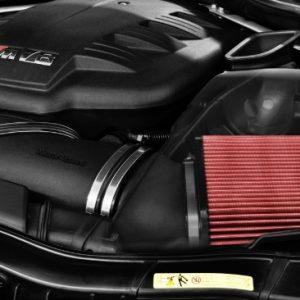
The F8X M3/M4 intake system is one of our most ambitious intake systems to date. Every detail was taken into account to ensure that we created a flagship intake to set a new benchmark for this platform. From the scoops to the ducts to the intake tubes – we developed a “complete solution” to ensure a smooth inlet track with cold air saturation. With a carbon weave to match the OEM M Performance carbon – this truly is a new benchmark.
The Eventuri Difference
The F8X M3/M4 Eventuri system uses our Patent Pending Carbon fibre Housing which provides an aerodynamically efficient airflow path from the filter to the MAF tube. Not just another cone filter with a heat shield but a unique design which invokes the Venturi affect. You can read more about the housing design and how it works HERE.
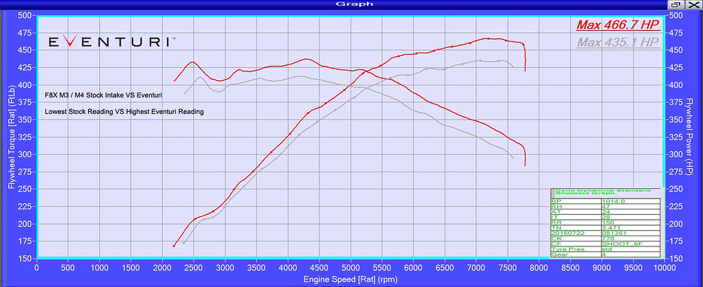
Below is a dyno graph showing the comparison between the Eventuri and the stock airboxes on a standard F80 M4. As you can see, power and torque are increased through a large portion of the rpm range not just at the peak. This translates on the road to increased part throttle and full throttle response with the car pulling much more eagerly to the redline. The testing was done on the same day back-to-back and temperatures were monitored to ensure consistency. Since dyno results vary between consecutive runs, this graph shows the highest power figure achieved with the stock setup vs the highest figure with the Eventuri.
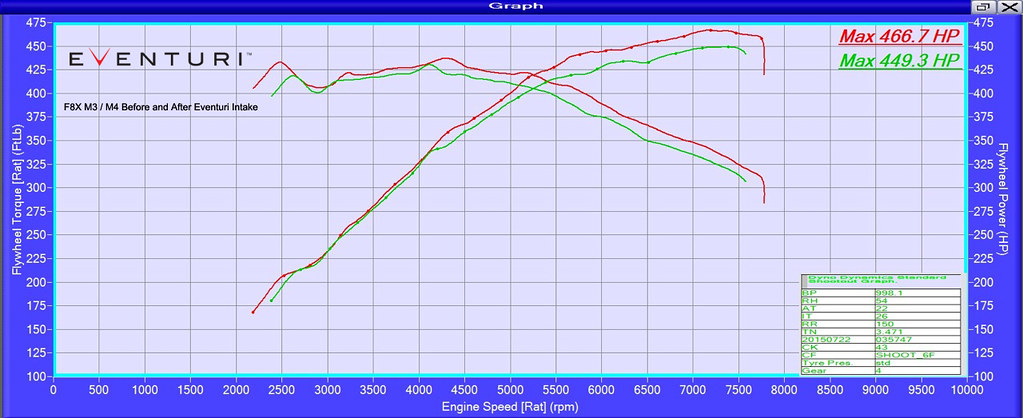
Since the F80 M4 is sensitive to heat soak, dyno figures can vary between runs – we could have shown the highest figure achieved with the Eventuri VS the lowest achieved with the stock setup, however this would not be a fair comparison. Just to illustrate the variation, here is the graph showing highest Eventuri VS lowest stock which was recorded on the day showing a gain of over 31hp!
Product Details
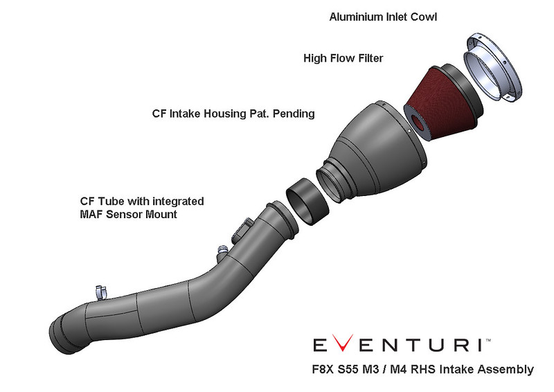
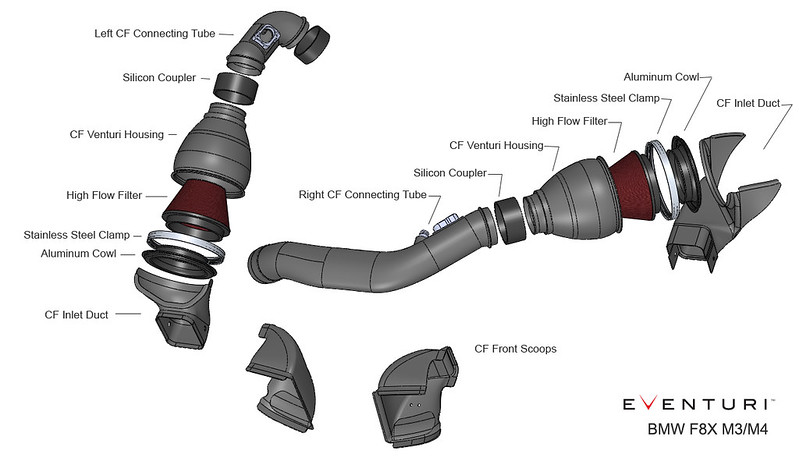
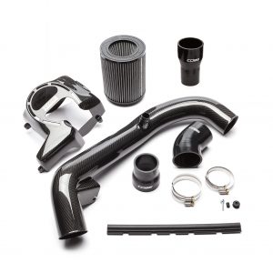
The Eventuri F8X M3/M4 intake system consists of a number of components engineered to perform a specific purpose and fabricated to the highest of standards. Here are the details for each component and the design ethos behind them:
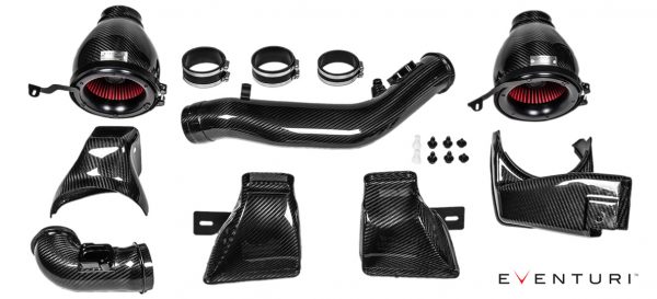
Each intake system consists of:
- 2 Carbon Fibre Venturi housings
- 2 High Flow Double Cone Air Filters
- 2 Aluminium Cowls for smooth airflow entry
- Left Side Carbon Tube with integrated MAF sensor mount
- Right Side Carbon Tube with integrated MAF sensor mount
- 2 Carbon Fibre Intake Ducts
- 2 Carbon Fibre Front Scoops
- Laser Cut Stainless Steel Brackets
- High quality Silicon couplers with BMW specification hose clamps
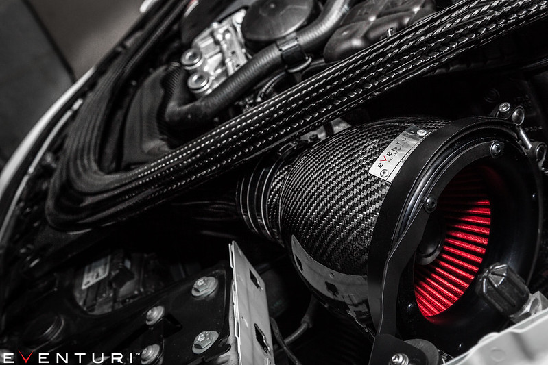
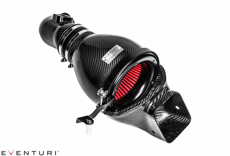
Carbon Intake Housing Assemblies
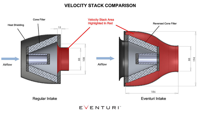
The filter housings comprise of the high flow filters, aluminium cowls, V-Band clamp, laser cut brackets and the carbon pods themselves. The carbon pods shroud the reverse mounted filter and smoothly shape the airflow down to the intake tubes. This smooth reduction in cross sectional area invokes the Venturi effect where the airflow accelerates whilst maintaining laminar conditions. It can be thought of as a large velocity stack – below is a diagram to show the comparison between our patent pending design and a regular intake system. Further details can be read in the Technology page.
Carbon Fibre Intake Ducts
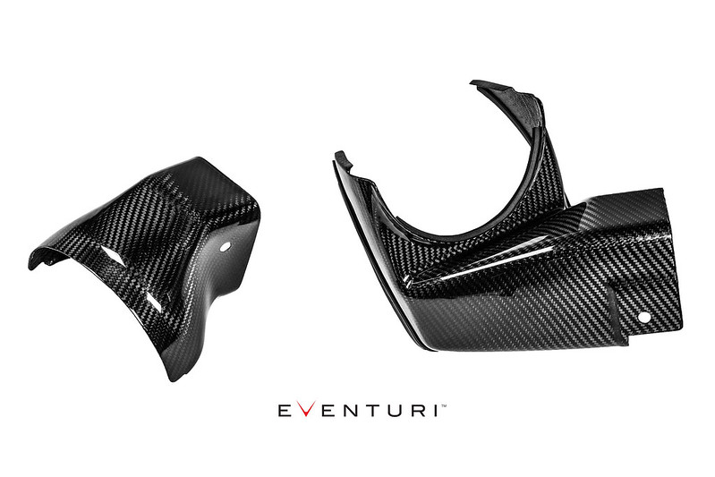
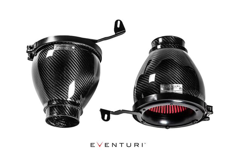
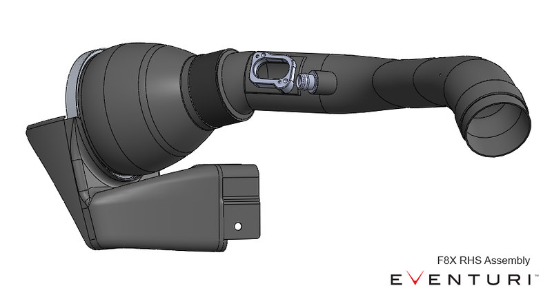
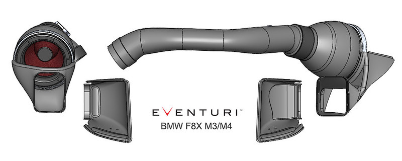
The filter housings are positioned with the openings nestled inside the intake ducts. These ducts have been designed to fit over the stock cold air ducts and direct ambient air into the filters. This ensures that the heated engine bay air is effectively displaced from around the filters whilst the car is in motion.
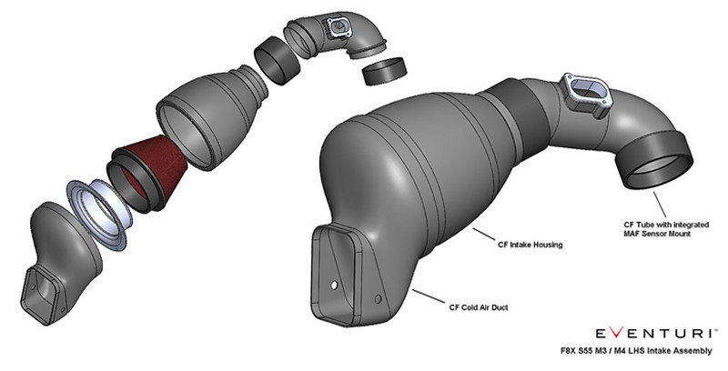
To illustrate – here are the left and right hand side intakes assembled as they would be in the engine bay with the tubes and ducts:
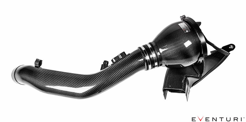
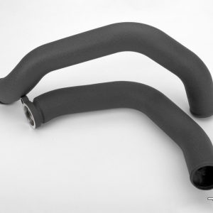
Carbon Fibre Intake Tubes
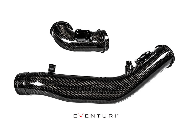
Our intake tubes are again crafted from 100% prepreg carbon fibre. Each tube has an integrated MAF sensor mount which is CNC machined from aluminium. The shorter left side tube smoothly transitions from the carbon housing down to the turbo inlet tube. The larger right side intake tube has to clear the fan shroud and strut brace. To do so we employed the same principle as the stock tube in changing the cross section from a circle at the turbo inlet tube to an oval for clearance over the shroud, then back to a circle at the filter housing end. We ensured these transitions were gradual so as not to disrupt airflow, furthermore we maintained the same cross sectional area in order to keep the velocity through the tube constant.
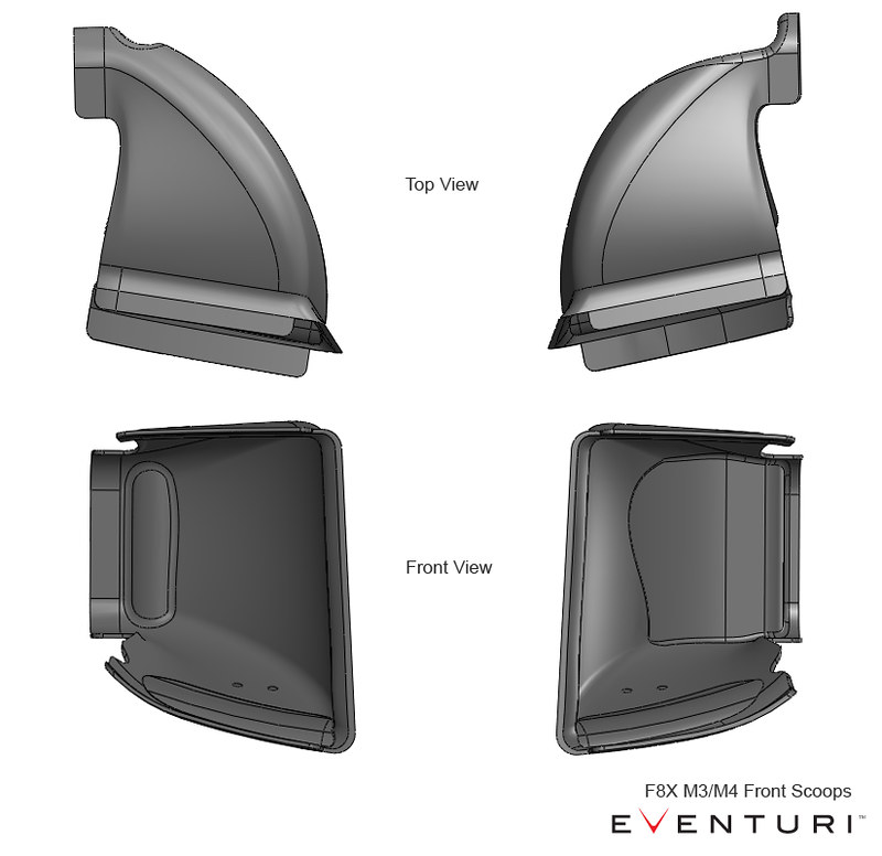
Carbon Fibre Air Scoops
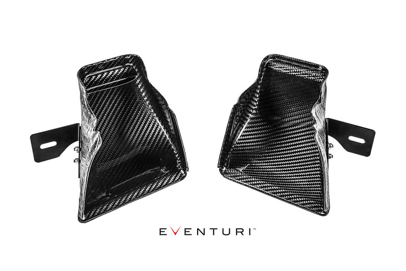

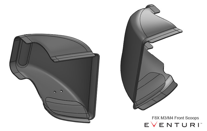
The final components in this system are the front scoops – essential to direct ambient air to the ducts and then to the filters.
The scoops were designed for maximum efficiency in directing the incoming air to the stock duct openings. Many aftermarket scoops have a large flat area almost perpendicular to the oncoming air – not great for channeling it into the ducts as the airflow just “hits” this flat portion and creates turbulence.
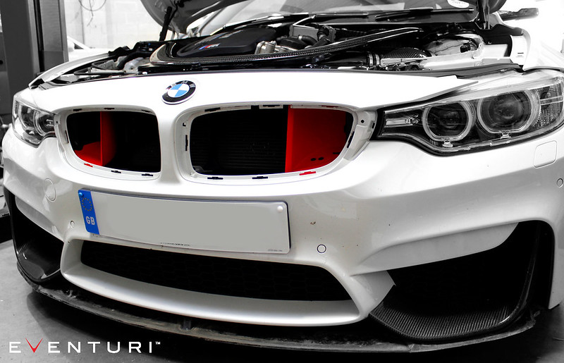
The Eventuri Scoops have been designed to sit directly behind the front grills to capture as much air as possible and with a continuous curve to the duct opening to ensure this airflow is efficiently channeled. CAD images to illustrate the shape:
Having an effective cold air feed to the filters is an essential part of our design. Simply having some heat shields in place is not an effective means of avoiding heated air from entering the filters unless the shields create an air tight envelope around the filters. The scoops and ducts in our system combine to provide the filter openings with ambient air and maintain low intake air temperature. To illustrate the effectiveness of this system, we put together this video:
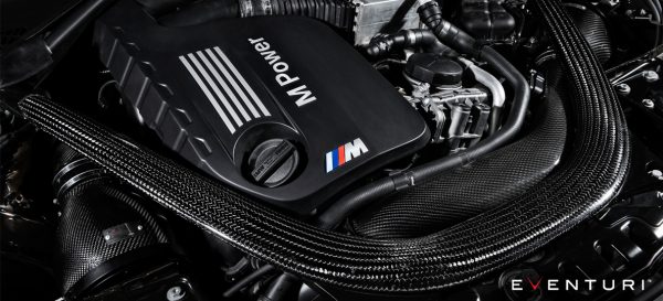
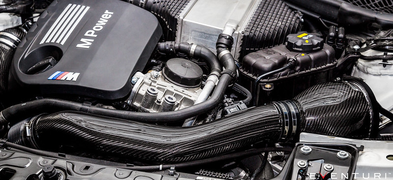
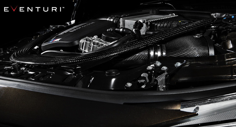
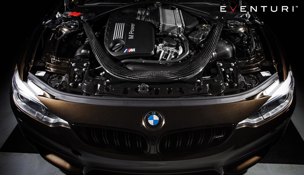
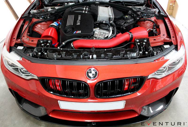
All the components come together in the engine bay to produce a genuine improvement in the driving experience as well as providing an incredible visual display of form and function in complete harmony.
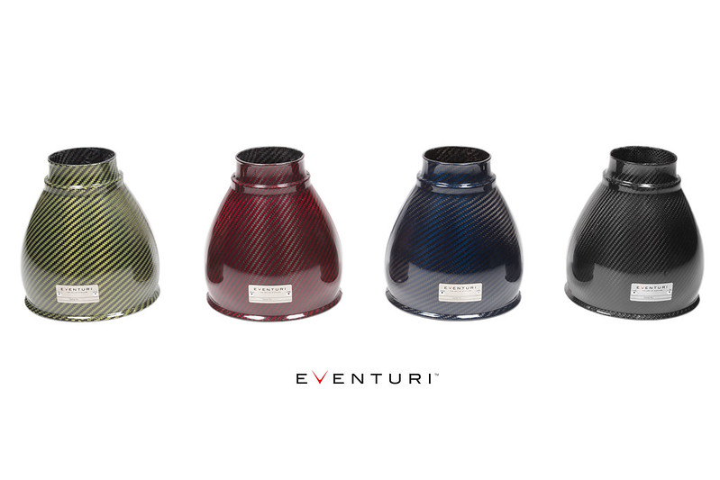
This intake system is available in black carbon fibre as well as a range of Kevlar options in Red, Blue, Yellow or Orange.
Development
The F8X M3/M4 Eventuri intake system was a culmination of months of dedicated design and development work. Here are some details of the development work and decisions which were made during the process:
A photo showing the final 3D printed prototype parts in place:
The aim as always was to develop an intake in order to make the inlet track of the engine more efficient therefore allowing the engine to make more power. To do this we had to carefully balance inlet temperatures requirements with a smooth path for airflow. Clearly lower IATs is best for power but then ensuring the inlet track is smooth is equally as important to allow the turbos to draw in air with as little drag as possible.
All our main components will be made from prepreg carbon fibre of the highest quality. We use CF because it is a great heat insulator across its thickness. We have seen other companies use Aluminium tubes etc which is a cheaper way of doing things but Aluminium is more than 400 times worse than CF at insulating the intake air from engine bay heat! So once the engine bay is heat soaked, metal tubes will get very hot and will heat up the inlet air as it travels through.
Filter Housings
The main component in our intake systems and the thing which sets us apart from other intake companies is our Venturi housing which is a unique take on the regular “cone filter with heat shield” design. It is a Patent Pending system where we reverse the cone filter to decouple it from the narrower inlet/MAF tube and the actual housing acts to then shape the airflow smoothly down from the large opening to the smaller outlet to the MAF.
Here’s a diagram to summarise the advantage of the design:
With the housing design completed to fit into the F8X engine bay we then proceeded with the tubing which also hold the MAF sensors.
LHS Intake
Looking at the engine, the left side has a short convoluted pipe going from the OEM airbox to the turbo inlet tube. In order to use our intake housing, we redesigned the tube, removing the ridges and importantly holding the MAF sensor.
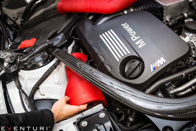
To direct ambient air to the filter, a duct was designed which fits over the stock intake duct from the bumper. Initially this was designed as a closed duct to completely cover the mouth of the housing:
However, CFD analysis pointed to turbulence caused by the abrupt change in direction from the stock duct to the filter – on dyno testing this was proven as we gained more power by opening the top of this duct.
So this was redesigned and now the duct directs and saturates the filter opening with ambient air without causing a restriction – a balance between IATs and airflow:
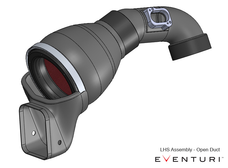
Although now semi-open, IATs are still kept consistently low with the front scoops which saturate the area in front of the filters with ambient air. More details on the scoops later.
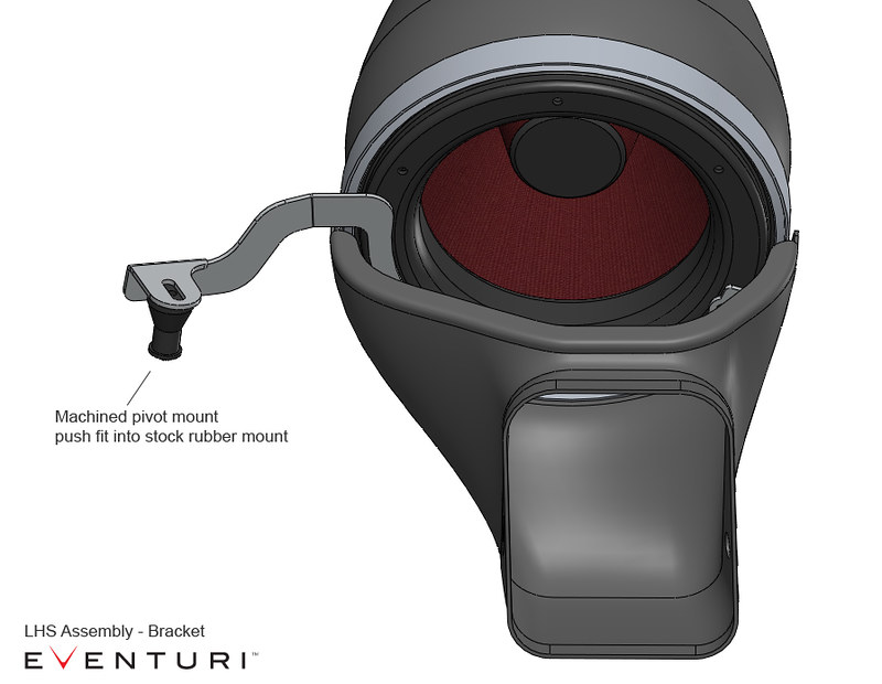
Now since we have removed the flexible stock tube and replaced it with a rigid CF tube, we needed to ensure some movement in the assembly in line with engine rotation and vibrations. So a mounting bracket was designed to slot into the stock rubber airbox mount. The bracket has a stub at one end which sits in the rubber mount and allows for adequate movement:
RHS Intake
For the right side, we redesigned the long tube to go from our filter housing to the turbo inlet tube. This longer tube has to clear the top of the radiator fan shroud but stay under the stock strut brace. In order to do so, like the stock tube, we transitioned the tube from circular at the connecting ends to oval in the middle for clearance. Importantly, we maintained a constant cross sectional area throughout the length downstream of the MAF sensor. By doing so the airflow maintains a constant velocity through the tube and the smooth geometric transitions help maintain laminar conditions.
Again – a duct was designed to capture ambient air from the stock ducts and direct the flow to the filters. Just like the analysis and testing carried out on the left side duct, we found that by opening the top of this duct, the system gained more power. Again – our scoops then ensure cold air saturation at the filter mouth.
Front Air Scoops
The final components in this system are the front scoops – essential in our system to direct ambient air to the ducts and then to the filters.
The scoops were designed for maximum efficiency in directing the incoming air to the stock duct openings. Many aftermarket scoops have a large flat area almost perpendicular to the oncoming air – not great for channeling it into the ducts as the airflow just “hits” this flat portion and creates turbulence.
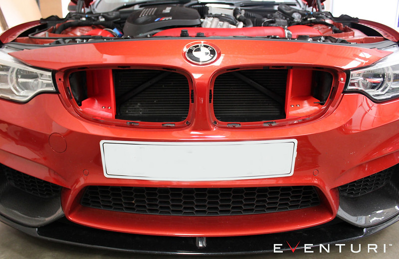
The Eventuri Scoops have been designed to sit directly behind the front grills to capture as much air as possible and with a continuous curve to the duct opening to ensure this airflow is efficiently channeled.
Here are the 3D printed prototypes in place – as you can see they capture the full area between the duct opening and the grills.

To illustrate the effectiveness of the scoop and duct designs we put together a demonstration using a leaf blower to simulate airflow. The comparison has been done between the Eventuri system and the stock system with the tops of the airboxes removed.
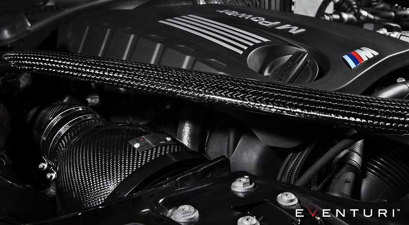
Full assembly photos:
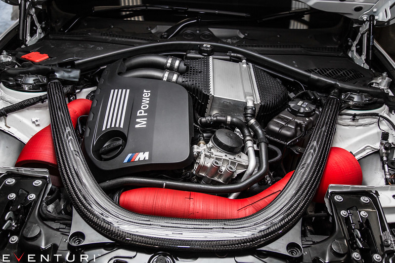
With the design completed we then moved onto production from Prepreg Carbon Fibre using the same weave as the OEM BMW M Performance 2×2 weave. Dyno testing was also carried out as results can be seen in the performance tab above.
Please download the installation guide here.

Reviews
There are no reviews yet.